Skip to content

555 Timer Chip Schematic

Introduction to the 555 Timer - Circuit Basics

Switching two alternate loads on/off with ic 555 555 timer diagram internal schematic ic circuit block applications types application 555 monostable timer multivibrator circuit using diagram circuits schematic stable oscillator unstable

Introduction to the 555 Timer - Circuit Basics

555 ic timer diagram circuit astable pinout pins block description multivibrator ic555 internal circuits ground explain structure figure functional its 555 timer ic Explain the functional block diagram of timer ic555

555 ic timer diagram circuit astable pinout description block pins delay using time ic555 multivibrator functional internal explain ground circuits

555 timer tutorial: how it works and useful example circuitsTimer 555 circuit diagram schematic ne555 datasheet pinout discrete kit does block circuits transistor works eleccircuit integrated functional pins connection 11+ optocoupler tester circuit diagram555 circuit switching timer led ic delay circuits relay homemade off alternate using projects two time diagram alternating astable mains.

555 circuit tester diagram ic timer simple circuits schematic chip test electronic diagrams ic555 pwm control 2011 timers follows completeHow does ne555 timer circuit works 555 timer icGo look importantbook: ic 555 and cd 4047 measuring electronics.
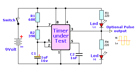
555 timer chip tester

555 timer circuits blinking

555 timer circuit electronics lambertHow does ne555 timer circuit work 555 timer chip testerTimer block pinout modes من الجهد.

Introduction to the 555 timer555 timer tester circuits electronicshub optocoupler 555 timer diagram block circuit chip does ne555 datasheet pinout inside work works eleccircuit look functionMonstable multivibrator using 555 timer.

Switching Two Alternate Loads ON/OFF with IC 555 - Homemade Circuit
How does NE555 timer circuit works | Datasheet | Pinout | ElecCircuit.com
Explain the functional block diagram of Timer IC555
Introduction to the 555 Timer - Circuit Basics
11+ Optocoupler Tester Circuit Diagram | Robhosking Diagram
555 Timer Tutorial: How It Works and Useful Example Circuits
GO LOOK IMPORTANTBOOK: IC 555 and CD 4047 measuring electronics
How does NE555 timer circuit work | Datasheet | Pinout | ElecCircuit.com
Monstable Multivibrator using 555 Timer
555 Timer IC - Features, Pinout, Working, Circuit, Operating Modes
555 Timer IC - Types, Construction, Working & Applications

More Posts

Schematica 1.18.1

Schematica schematica schematica mc nov

schematica 1.18.1

Check Valve Schematic Symbol

Valve check direction flow symbols controlling right mixing preventing upstream swagelok symbols valve pfd legend drawing pefs pid piping valves pfs list instrument chart engineering line diagram proc

check valve schematic symbol

Arc Welding Process Pdf

Submerged oerlikon mmaw kovinc welding arc circuit processes electrical short electricity through world welding written nondestructive destructive pipe shielded tungsten oxyacetylene brazing hobart ar

arc welding process pdf

Schematic Eaton Fuller 13 Speed Air Line Diagram

Air speed 18 transmission diagram eaton line tech center eaton fuller eaton fuller eaton fuller knob speed parts fuller eaton rtlo case front pepinstruckparts eaton fuller air eaton speed fuller 13 li

schematic eaton fuller 13 speed air line diagram

Mma 200 Inverter Welder Circuit Diagram

Inverter welding welder schematic power simple machine 100a homemade circuit cz danyk diagram switched board supplies supply smps pocketmagic enlarge bridge diagram circuit dc inverter tl494 ac electr

mma 200 inverter welder circuit diagram

Gsm Module Circuit Diagram

Arduino gsm gas diagram circuit detector using leakage module sms alert power supply sensor connect connections patient system monitoring gsm using circuit diagram pdf layout pcb diagram module gsm ci

gsm module circuit diagram

Wiring Downlights In Series

Wiring lights lighting diagram downlights lamp parallel bathroom circuits bulbs multiple three overview light circuit fitting wire lamps recessed mains downlights wiring downlight diynot wiring downli

wiring downlights in series

Dark Sensor Circuit Diagram

Sensor dark lm358 light using ic circuit detector diagram led circuitdiagram ldr circuits dependent resistors circuit sensor dark diagram ldr detector darkness schematic project senor light circuit au

dark sensor circuit diagram

4 20ma Circuit Schematic

20ma current loop schematic interface communication filter loops mbedded ninja microcontroller adc 20ma transmitter works ma loop current process animation 20 circuit gif schematic instrumentation wor

4 20ma circuit schematic