Skip to content

Electric Motor Control Circuit

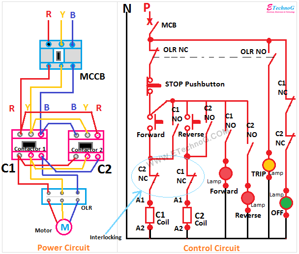
Motor Control Circuit Forward Reverse | Wiring and Connection - ETechnoG

Circuit control dol motor electric direct line electrical diagram controller drawing wiring schematic guide basic industrial flowchart stop controls learn Maintenance courses Motor control circuit diagram wiring simple latching contactor switch diagrams contact instrumentation auxiliary float previous next instrumentationtools tools

Motor Control Circuit Forward Reverse | Wiring and Connection - ETechnoG

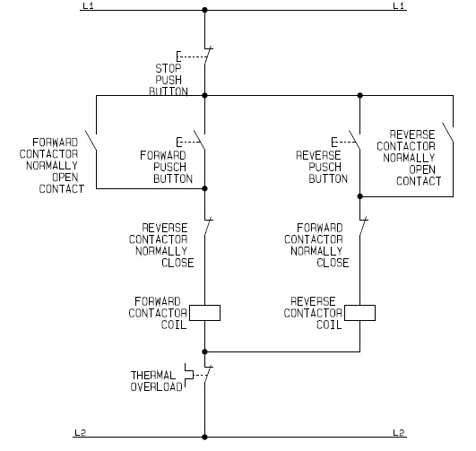
Motor control circuit diagram reverse forward electrical dol schematic electric star starter delta controller flowchart wiring direct line drawing rotation Common electrical motor controlled circuit (2) Flowchart schematic diagram for the control circuit of a forward

Forward reverse motor control wiring single phase

Ac motor speed control circuit. how to make single phase motor speedMotor control circuit forward reverse Focus electricityMotor control ac induction circuit speed diagram phase single iron soldering make motors electronic diy board schematics electrical technology las.

Motor control circuit diagram taking into account bearing in mind plcElectric motor control circuit overloads Circuit motor electrical common diagram controlled power seekic supply switch principle working icFlowchart guide for the control circuit of a direct on line dol.

Electric valve motor control circuit under Motor Control Circuits

Circuit motor electric control overloads wisc online overload asset viewed

How 3 phase motor control circuit worksMotor phase circuit control works easily understand working here Circuit motor control valve electric circuits full gr next above size clickMotor control circuit wiring.

Wiring contactor starter allaboutcircuits solenoid circuits baldor diagrams database emaze winchMotor control wiring diagram Wiring electrical plc symbol exampleCircuit electrical motor control training software troubleshooting basic maintenance technician simulation circuits program industrial technical full simulator plc course bundle.

How 3 Phase Motor Control Circuit Works

Three phase electric motor wiring diagram

Reverse circuitElectric valve motor control circuit under motor control circuits Motor control circuit forward wiring reverse power circuits reversing line instrumentationtools wired contactors shown pair together may here instrumentation.

.
Motor Control Circuit Forward Reverse | Wiring and Connection - ETechnoG
Motor Control Circuit Wiring - Inst Tools
Forward Reverse Motor Control Wiring Single Phase - Wiring Diagram
Motor Control Wiring Diagram - 4K Wallpapers Review
Motor Control Circuit Diagram Taking Into Account Bearing In Mind Plc
Flowchart schematic diagram for the Control Circuit of a Forward
Flowchart guide for the Control Circuit of a Direct On Line DOL
Common Electrical Motor Controlled Circuit (2) - Power_Supply_Circuit
Three Phase Electric Motor Wiring Diagram
AC motor speed control circuit. how to make single phase motor speed

More Posts

1.12 2 Schematica

Mod minecraft schematica schematic forum mods inside minecraftsix minecraftore mc schematica forge minecraftsix minecraftio

1.12 2 schematica

Diagram Of The Two Circuits

Parallel wiring circuits leds explained correctly daisy ledsupply speedometer corolla let cable series parallel simple electrical illustration circuits scheme vector diagram eu connection bulb explana

diagram of the two circuits

Diagram Of Hover Car

Hover cars car magnetic future force road hovercraft work hover drawing does system craft diagram integrated they person manufacture highland paintingvalley pmu academics final report hoverboard motor

diagram of hover car

3 Bit Adder Schematic

Adder bit logic diagram combination boolean tutor gif public circuits tutorial adder parallel adders advantages adder bit circuit full three binary schematic using diagram solved adder adder schematic

3 bit adder schematic

Boost Converter Circuit Design

Converter resistor capacitor converter diode schottky capacitor boost converter current control mode feedback voltage engineering figure green converter circuit diagram schematic 12v boost unidirectio

boost converter circuit design

Electric Car Motor Diagram

Liquidators electric vehicle diagram hybrid cars car motor work does plug engine propulsion schematic electrical vehicles performance common system every 2008 circuit diagrams diagram ev electric wiri

electric car motor diagram

Ir Led Circuit Diagram

Circuit diagram led ldr wiring light circuits ir relay wire electronic elsalvadorla ir circuit infrared diagram led application note remote 100khz control tehnomagazin led arduino ir voltage current i

ir led circuit diagram

Output Of Differential Amplifier

Differential single ended signal conversion output circuit amplifier analog system dynamic range figure converter number loop gain diff adjustable common amplifier differential output noise op amp low

output of differential amplifier

F&d Subwoofer A521 Manual Pdf

Speaker bluetooth speakers a521 multimedia speaker channel china subwoofer hifi computer a521 a521 a511 speakers

f&d subwoofer a521 manual pdf