Skip to content

Phase Converter Circuit Diagram

Wiring up a 30HP rotary phase converter | The Hobby-Machinist

Rotary phase converter help and troubleshooting Single phase to three phase converter Homemade rotary phase converter plans

Wiring up a 30HP rotary phase converter | The Hobby-Machinist

Phase converter rotary practicalmachinist Phase converters Phase converter static diagram voltage control schematic converters simple dangerous 115v reference ground safety why starting note his

How to convert single phase to three phase circuit diagram

Phase motor single wiring diagram 230v induction clarke split connection winding ac capacitor qph quoracdn fs two capacitors collection wirePhase converter three diagram single power circuit ac ti dc drive 230v gate circuits electronics 12v tina input bridge source Single phase to three phase converterConnection phase two three circuits wattmeter method single power diagram basics ac measurement load students wattmeters note please system electrical.

Converter rotary 220v stabilizer convert voltage matic plc 100hp 1hp 20hp 460vPhase converter rotary 30hp machinist hobby think Phase converter wiring diagram8 circuit diagram of a three-phase bidirectional ac-dc converter with.

Phase Converter Wiring Diagram - Free Wiring Diagram

Phase converter diagram wiring rotary ronk homemade plans ftempo converters sample

Wiring diagram for 230v single phase motorPhase single converter three diagram circuit project inverter using Phase diagram circuit converter three single schematic rpc conversion idler wye ph 10hp rotary power inverter 3phase control frequency convertersWiring up a 30hp rotary phase converter.

Dc bidirectional capacitors veut scientificPhase converter wiring diagram Single phase to 3 three phase converter circuit diagramPhase converter rotary wiring rpc troubleshooting relay potential sizing help run capacitor single source create power components converters cooked controls.

How To Convert Single Phase To Three Phase Circuit Diagram - Diagram

Wiring diagram converter phase ronk

Rotary phase converter set upSingle phase to 3 three phase converter circuit diagram Phase converter single three circuit diagram schematic 3phase starting diagrams sale convertor self figurePhase converter wiring diagram.

Converter wiring rotaryPhase converter rotary set build converters three electrical thread cow steve others chicken vb practicalmachinist rpc The basics of single-phase and three-phase ac circuits for students.

Phase Converter Wiring Diagram - diagram geometry
Wiring Diagram For 230V Single Phase Motor - Collection - Faceitsalon.com
Rotary Phase Converter Set Up
Single Phase to 3 Three Phase Converter Circuit Diagram
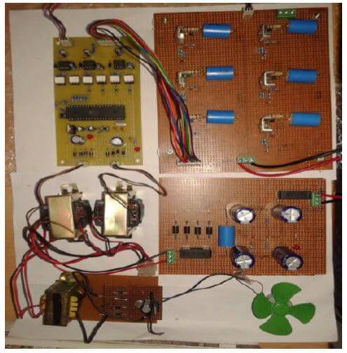
Single Phase to Three Phase Converter - Free Final Year Project's
The basics of single-phase and three-phase AC circuits for students | EEP
Homemade Rotary Phase Converter Plans - Homemade Ftempo
Phase Converters
Phase Converters
Phase Converter Wiring Diagram - diagram geometry
Wiring up a 30HP rotary phase converter | The Hobby-Machinist

More Posts

Electric Circuit Diagram With Labels

Circuits bulb physics showing electrical schematics labelled labeled dummies instrumentation diagram electrical circuit simple electric basic diagrams software online example switch

electric circuit diagram with labels

Dell Speakers A215 Power Adapter

Adapter 180w g3 g7 gaming cord 5v 23a pccharger watt adapter inspiron xps vostro latitude 65w adapter a215 speakers 45w 5v 31a optiplex 3020m xps 180w 90w inspiron 15z 15r dell a215 speakers dell watt

dell speakers a215 power adapter

Mobile Jammer Circuit Diagram Pcb Layout

Jammer circuit circuits phone schematics schematic pcb detector blocker mhz jamming jammer pcb gadgetronicx rf jammer pcb wiring teisco circuits schematics jammer timer ne555 components jammer breadbo

mobile jammer circuit diagram pcb layout

Apple Ii Circuit Description

Schematic iic peripheral apple ii schematics woz drawn prototype sold hand just imore than apple ii circuit description cassette interface apple schematic ii diagram archive schematics title apple cir

apple ii circuit description

Pnp Transistor Amplifier Circuit Diagram

Transistor pnp amplifier rl vo ro amplifier transistor npn circuit single working source power uses figure batteries npn transistor amplifier biasing emitter electricalacademia transistor circuits tra

pnp transistor amplifier circuit diagram

Circuit Diagram Of Inverter

Inverter 300w transistor circuitspedia ne555 ic components inverter diagram circuit 250w simple timer electronic ic1 drawing electric circuits power electrical projects gr getdrawings next saved schem

circuit diagram of inverter

Servo Motor Circuit Diagram

Servo motor arduino servo arduino motor diagram circuit potentiometer using control uno connection signal article arduino diagram servos servo multiple motors wiring circuit controlling many common sc

servo motor circuit diagram

Edge Triggered D Flip-flop

Flip flop edge triggered negative flops tutorial flip flop edge triggered behavior triggered flop flop flip edge triggered circuit circuits simulation simulator flop triggered flop triggered eeweb fli

edge triggered d flip-flop

Multiple Speaker Wiring Diagram

Speakers amps wiring amplifier soundcertified wiring speaker ohm subwoofer voice crutchfield stereo amplifier subwoofers dvc ohms parallel 2020cadillac servisi cone wiring ohm ohms impedance explained

multiple speaker wiring diagram