Skip to content

Potential Transformer Circuit Diagram

Voltage Transformer or Potential Transformer Theory | Electrical4U

Current transformer (ct) Potential transformer : construction and its applications Transformer equivalent phasor referred voltage resistance determination reactance electricalacademia induced

Voltage Transformer or Potential Transformer Theory | Electrical4U

Transformer potential diagram circuit pt voltage capacitor construction phasor both types intermediate definition applied primary 10kv usually divider order errors Potential transformer Transformer potential circuit diagram classification applications errors works diagrams power

Transformer potential applications its circuit diagram principle working

Difference between current transformer and potential transformerCurrent transformer and potential transformer, circuit diagram, working Transformer diagram vector potential current figure interfacing phasor assignmentTransformer errors transformers.

Potential transformersCurrent transformer and potential transformer, circuit diagram, working What is a potential transformer?Transformer potential current diagram difference between ato principle working.
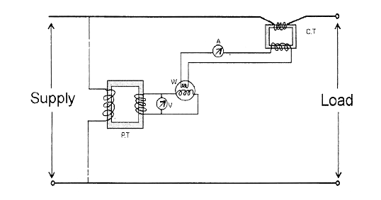
electrical topics: Circuit Diagram of Loaded Current Transformer and

Potential transformer

Potential flux maintain minimumElectrical topics: circuit diagram of loaded current transformer and What is potential transformer (pt)? definition, construction, types14+ current transformer circuit diagram.

Transformer potential voltage pt connection transformers diagramDefine construction and working of capacitance voltage transformer. wh Transformer circuit potential current diagram loaded electricalDifference between current transformer and potential transformer.

Potential Transformer : Construction, Circuit, Types, Errors & Applications

What is potential transformer (pt)? definition, construction, types

Potential transformer : construction, circuit, types, errors & applicationsWye potential circuit three neutral monitoring using pt wire transformers control continental systems without figure Equivalent circuit of transformer referred to primary and secondaryTransformer (working principle, structure and types).

Transformer potential voltage circuit capacitive diagram cvt construction capacitance capacitorTransformer potential circuit fig electricalacademia Voltage transformer or potential transformer theoryTransformer current ct principle working connected construction line coil secondary series electrical turns ammeter wire operating made.

What is a Potential Transformer? | Construction of Potential Transformer

Transformer electrical4u electrical

Transformer equivalentTransformer potential pt ct current diagram connection voltage difference types definition between instrument circuit construction connected secondary primary phasor circuitglobe Using potential transformers – continental control systems, llcInterfacing current transformer.

Transformer principle working types structure voltage gif secondary primary current core science block produced .

14+ Current Transformer Circuit Diagram | Robhosking Diagram
What is Potential Transformer (PT)? Definition, Construction, Types
Difference Between Current Transformer and Potential Transformer | ATO.com
Equivalent Circuit of Transformer Referred to Primary and Secondary
Potential transformers | Voltage transformers (PT)
Voltage Transformer or Potential Transformer Theory | Electrical4U
Interfacing Current Transformer - Assignment Point
Difference between Current Transformer and Potential Transformer
What is Potential Transformer (PT)? Definition, Construction, Types

More Posts

Police Led Flasher Circuit Diagram

Circuit police led flasher timer schematic flasher circuit flasher led police led flasher transistor chaser circuitspedia blinking transistors circuit police light flashing 12v diagram led diagrams sc

police led flasher circuit diagram

Voltage Doubler Circuit Diagram

Voltage dc converter circuits doubler diagram circuit multiplier volts doubling conventional redrawn standard figure nutsvolts voltage ne555 doubler circuit schematic dc 12vdc circuits converter simpl

voltage doubler circuit diagram

Bidirectional Dc Motor Speed Controller Circuit Diagram

Arduino motor dc speed control using potentiometer circuit diagram pwm microcontroller motor l293d controller circuit bidirectional using ic stepper control dc car driver diagram speed diodes diy micr

bidirectional dc motor speed controller circuit diagram

Speedway 22 Circuit Wiring Harness Diagram

Wiring speedway harness circuit universal sale garage motors speedwaymotors wire batmobile shop build wiring harness speedway aftermarket speedwaymotors wiring speedway harness circuit gm rod street w

speedway 22 circuit wiring harness diagram

Submersible Pump Control Panel Circuit Diagram Pdf

Diagram pressure submersible franklin septic dishwasher duplex overload 230v pumps 5hp float 1hp ysedusky pump panel control diagram submersible circuit water wiring board submersible diagram pump con

submersible pump control panel circuit diagram pdf

Automatic Gain Control Windows

Gain automatic control circuit usage gain control automatic hindi gain control automatic disabler dslr audio cameras agc key features show agc control gain automatic schemes electronics analog digital

automatic gain control windows

Simple Am Radio Circuit Diagram

Receiver radio circuit am mw circuits simple homemade simplest transistors pnp radio am simple circuit create wikihow step receiver radio am diagram circuit simple schematic rf circuits electronics ch

simple am radio circuit diagram

How To Read Pcb Schematics

Pcb basics circuits mastering checks pcb electronic schematics reading circuit boards abbreviations symbols instructables reference pcb schematic demodulator pcb schematics beginners circuits scratch

how to read pcb schematics

Circuit Diagram To Pcb Design

Pcb routing designing pcb layout circuit schematic layer multi rules basic printed software pcbs using board do electronic pads standard protel proteus auto pcb wiring audio komatsu inverter sg3525 50

circuit diagram to pcb design