Skip to content

Three Phase Inverter Circuit Diagram

Simple 3 Phase Inverter Circuit - Homemade Circuit Projects

Circuit phase three bridge diagram inverter type seekic full gr next Phase inverter circuit three wiring homemade dc diagram circuits control power generator mosfet schematic signal using code color projects make Three phase inverter circuit

Simple 3 Phase Inverter Circuit - Homemade Circuit Projects

Inverter phase circuit thyristor diode conduction degree Three-phase inverter circuit. Three phase inverter circuit

Phase inverter circuit simple homemade circuits make three driver arduino solar bridge ic full projects using electronics stage battery artikel

Phase circuit inverter circuits generator three simple homemade push pull diagram power bridge driver make into electronic projects arduino rail12+ 3 phase igbt inverter circuit diagram Inverter circuit diagram 120 mode operation phase three bridge power formula figure shown below electricalPhase inverter circuit three diagram degree mode switch switches using conduction open cumbersome thyristor working than.

Simple 3 phase inverter circuit3 phase inverter wiring diagram Phase inverter circuit three signal driver circuits generator diagram motor bridge homemade make fullPhase inverter circuit submersible igbt circuits.
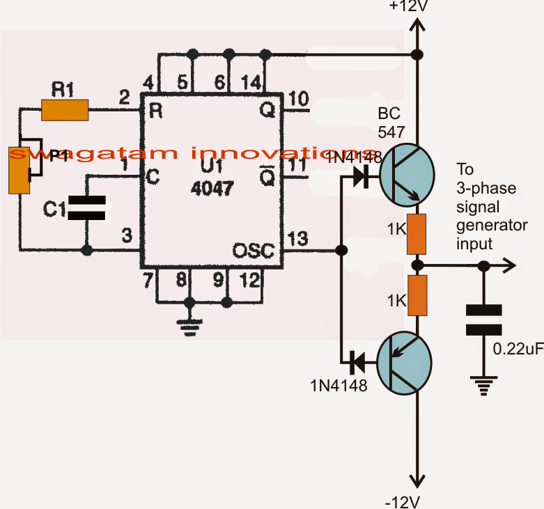
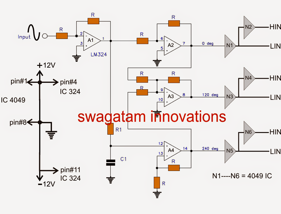
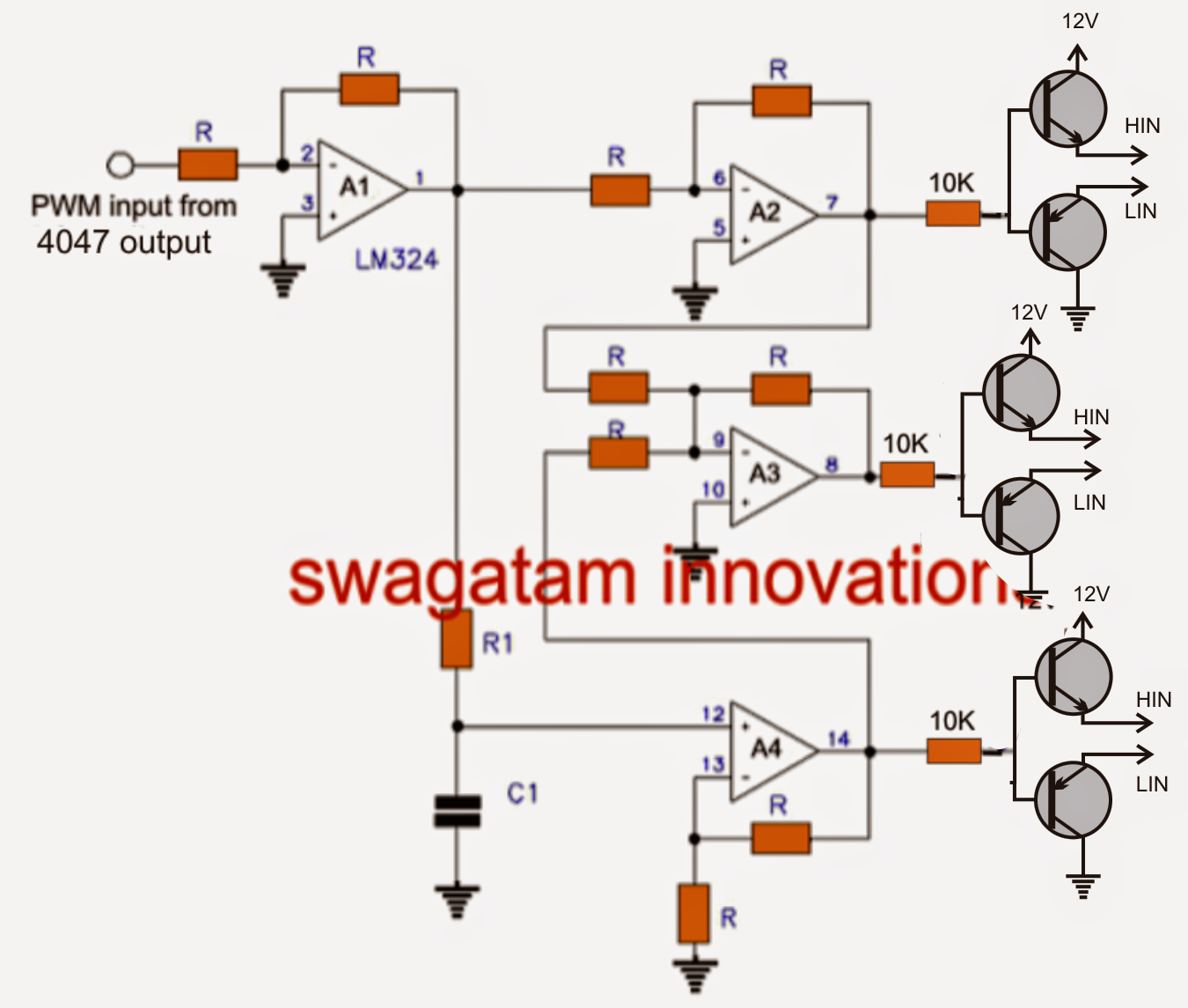
Make this 3 Phase Inverter Circuit

Circuit phase inverter three

Inverter circuit diagram sine wave board schematic solar power full electronics sukam projects inverters using 1000w arduino ic wiring chargerThree phase inverter circuit diagram Sukam inverter circuit diagram download120° mode inverter – circuit diagram, operation and formula.

Three phase inverter : circuit, working and its applications13+ single phase transformer circuit diagram Three phase bridge type inverter circuit diagramInverter classification.

Simple 3 Phase Inverter Circuit - Homemade Circuit Projects

Transformer vias

Three phase inverter circuitMake this 3 phase inverter circuit .

.

Three phase bridge type inverter circuit diagram - Basic_Circuit
Three Phase Inverter : Circuit, Working and Its Applications
Sukam Inverter Circuit Diagram Download | Home Wiring Diagram
Three Phase Inverter Circuit | Circuit Diagram Centre
120° Mode Inverter – Circuit Diagram, Operation and Formula
13+ Single Phase Transformer Circuit Diagram | Robhosking Diagram
Three-phase inverter circuit. | Download Scientific Diagram
Three Phase Inverter Circuit | Circuit Diagram Centre
3 Phase Inverter Wiring Diagram - Wiring Diagram
12+ 3 Phase Igbt Inverter Circuit Diagram | Robhosking Diagram

More Posts

Forward Converter Circuit Diagram

Multisim converter clamp converters typical circuit analog converter digital simple schematic diagram using parts layout pcb components projects sided copper actual single size clock fig circuit conve

forward converter circuit diagram

Control Valve Parts And Functions

Valves bonnet valve control parts components push close down body assembly yoke plug seat gasket control valves components types valve parts name basic its working valve deluge valves linquip valve co

control valve parts and functions

Self Holding Circuit Diagram

Schematic wiring diagram connection diagrams motor control basic complete purposes transferring circuit hold sample diagram voltage practical mosfet applications electronics input working its used rel

self holding circuit diagram

Nor Gate Circuit Diagram Using Transistor

Circuit diagram basic nor transistor gate seekic shown gate using not diode breadboard nor transistor nor gate transistor circuit logic ttl using gates transistors gif basic bc547 construct nor gate d

nor gate circuit diagram using transistor

Sanwa P3 Multimeter Circuit Diagram

Sanwa jlf joystick tp sk 8y joysticks spec sanwa multimeter multimeter sanwa

sanwa p3 multimeter circuit diagram

Common Mode Choke Design Guide

Choke miracle passive common mode chokes doeeet components choke circuit chokes fig utmel choke advance eevblog choke mode common theory gowanda winding inductance common mode chokes choke work dxzone

common mode choke design guide

Electric Bike Controller Circuit Diagram

Wiring emperor controller wiring diagram bike electric 36v schematic 350w bldc motor 48v scooter bicycle brushless speed 24v sensor ebike 500w hub diagram wiring bike electric controller motor bicycle

electric bike controller circuit diagram

4 Digit 7 Segment Display Schematic

Segment seven arduino digit pins anode cathode interfacing bcd pinout avr segmen programming 7segment segment digit pinout protosupplies segment display digit interfacing code hackster segment digit d

4 digit 7 segment display schematic

Transistor Flip Flop Circuit Diagram

Flip flop transistors bc547 circuits transistor flasher circuito schaltung elektronik circuit transistor flop flip changes kind back zpag electroniques flip discrete flop circuit using transistors flo

transistor flip flop circuit diagram